Expanded Metal Mesh Sheet For Fencing

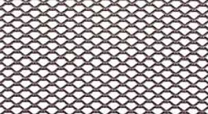
Plane solid sheets or plates of aluminum, stainless steel, titanium, silver, nickel and a variety of nickel alloys are used for the production of expanded metal. As the expanded metal is fabricated from a metal sheet and it is not woven or welded hence it doesn’t deform.

For the fabrication of expanded metal, a sheet is simultaneously slit and stretched; it expands the cuts into diamond shape holes of equal size and shape. As the process doesn’t cause any metal loss while expanding the metal, the resulting product is more economical.

While selecting an expanded metal for fence application you will require to find which type or diamond size is suitable for your fencing application. Expanded metal designations are described by SWD (short way of diamond), metal gauge, weight per hundred sq. foot etc.

Another factor to consider while ordering the expanded metal mesh panels is actual metal strand width and strand thickness. These are essential as they are essential for opening size of diamond and open area% or visibility through fence.

Heanjia Super-Metals has standardized it for fencing requirements. Following is the commonly used specifications for expanded metal for fencing applications.

Style weight/sq. ft Diamond size, in Diamond opening size, in Strand size, inch Open area
SWD LWD SWO LWO Width Thickness
Carbon steel standard expanded
½ in-13R 1.74 0.500 in 1.20 in 0.312 in 0.938 in 0.096 in 0.090 in 57 %
½ in-13R 3.1 0.500 in 1.20 in 0.220 in 0.630 in 0.188 in .090 in 25 %
¾ in – 9R 1.98 0.923 in 2 in 0.688 in 1.562 in 0.150 in .134 in 68 %
1 in – 7R 3.7 1 in 2.40 in 0.650 in 1.6 in 0.240 in .170 in 39  to 41 %
1 in- 7R 4.79 0.875 in 2.20 in 0.450 in 1.550 in 0.275 in .183 in 52 %
1-1/2 in – 6R 2.75 1.330 in 3 in 1.110 in 2.313 in 0.203 in .194 in 69 %
1-1/2 in – 9R 1.31 1.330 in 3 in 1.125 in 2.375 in 0.144 in .134 in 76 %
2 in – 9R 0.99 1.850 in 4 in 1.563 in 3.375 in 0.149 in .134 in 84 %
Flattened
½ in – 13F 1.61 0.500 in 1.25 in 0.265 in 1 in 0.107 in .078 in 52 %
¾ in – 9F 1.88 0.923 in 2.10 in 0.563 in 1.688 in 0.165 in .120 in 63 %
1-1/2 in – 9F 1.25 1.330 in 3.20 in 1 in 2.563 in 0.158 in .110 in 75 %
Stainless steel 304
½ in – 13R 1.87 0.480 in 1.20 in .270 in .830 in .113 in .093 in 52 %
¾ in – 9R 2.05 .923 in 2 in .687 in 1.562 in .160 in .140 in 67 %
1-1/2 in – 9R 1.37 1.330 in 3 in 1.125 in 2.500 in .155 in .140 in 77 %
Flatness stainless steel
½ in – 13R 1.78 .48 in 1.26 in .220 in .970 in .128 in .080 in 47 %
¾ in – 9R 1.95 .923 in 2.10 in .562 in 1.697 in .165 in .119 in 61 %
1-1/2 in – 9R 1.31 1.330 in 3.15 in .937 in 2.625 in .165 in .119 in 75 %
Aluminum
½ in – .081 .44 .500 in 1.20 in .375 in .937 in .096 in .081 in 60 %
¾ in -.125 .65 .923 in 2 in .687 in 1.680 in .169 in .125 in 68 %
1-1/2 in – .125 .43 1.330 in 3 in 1.187 in 2.5 in .162 in .125 in 79 %
Flattened aluminum
½ in -.081 .42 .500 in 1.27 in .312 in 1 in .105 in .060 in 58 %
¾ in – .125 .62 .923 in 2.13 in .625 in 1.750 in .187 in .095 in 62 %
1-1/2 in – .125 .41 1.330 in 3.15 in 1 in 2.750 in .181 in .095 in 70 %


SWD (short way diamond) and LWD (long way diamond) are commonly used designations. The diamond’s orientations develop a different look for the fencing applications. An expanded metal mesh panels can be configured in two ways – standard and reversed diamond orientation.

Reverse diamond orientation:-

Expanded metal is specified as SWD x LWD.

Standard and flattened expanded metal:

Standard expanded sheet plate delivered as it is received from the press. It has good strength and is commonly used for the fencing applications.

Flattened expanded sheet is produced by passing the metal through cold roll reducing mill parallel to the LWD. Through flattening, the bonds and strands are settled down to create a smooth and flat surface.


Tagged with: , , ,
Posted in expanded metal, Uncategorized

Sintered metal filter solutions

Heanjia Super-Metals is a global leader in the production and supply of filtration and separation products. We have a manufacturing unit in China and sales branch in America to connect with channels across the planet. Our specialization is extensive and wide over 32 years serving the industries such as nuclear, energy conservation, aerospace and military, medical, porous media and components, water processing, printing and food processing.

Our success is defined by our technical specialization and wide customer support. Our R & D department ventures to provide creatively new products that outperform the needs of our clients in meeting their requirements.

We are engaged in producing a wide range of stainless steel filter products fit for use in the various industries such as petrochemical. The firm design is needed to prevent damage in the severe service conditions where the fluids are aggressive, elevated temperatures are experienced or where the service differential pressures are large. In few filtration applications, using traditional polymeric cartridge may be inefficient and using recleanable materials will prove to be economical filtration solution.

The filter elements produced are – Sintered metal fiber and sintered metal mesh. The cylindrical mesh design offers a sleeve of filter medium (made from woven wire mesh) on a support core. The pleated cartridge design utilizes a precision sintered pack on a support core to offer an effective filtration material in a cylindrical shape. In these designs, the filter media and support mesh are TIG welded and media support core and end fittings are TIG welded. This method ensures filter integrity, preventing the risk of leakage and availability of extractables received from the bonding materials. The production technique and materials for service from -238oF to 572oF or -150oC to 300oC and about 367 psi or 25 bar differential pressure in normal flow direction. Elevated service temperatures and various pressures can be handled by the sturdy mesh design.

In double open ended system, internal core supports the position of multiple length shapes onto tie rods. The sintered cartridge style has an external guard security and to permit for back flushing about 44 psi.


Base pipe size, inch Base pipe, weight lbm/ft Assembly weight, lbm/ft Base pipe Id, Inch Maximum screen Outer Dia, inches Count of perforated holes per ft Highest tensile rating, lbf Highest torque rating, lbf fy Highest collapse rating, psi Highest burst rating, psi
2.375 in 4.6 lbm/ft 3 lbm/ft 2 in 2.99 in 48 58,446 lbf 2400 9300 psi 2028 psi
2.875 in 6.4 lbm/ft 3.6 lbm/ft 2.44 in 3.49 in 60 82,823 lbf 4200 8800 psi 1749 psi
3.85 in 9.2 lbm/ft 4.2 lbm/ft 2.99 in 4.11 in 72 115,926 lbf 7300 8300 psi 1495 psi
4 in 9.5 lbm/ft 4.6 lbm/ft 3.55 in 4.61 in 84 152,710 lbf 9900 5000 psi 1338 psi
4 in 11 lbm/ft 4.6 lbm/ft 3.48 in 4.61 in 84 165,261 lbf 11,100 6600 psi 1338 psi
4.5 in 11.6 lbm/ft 5.4 lbm/ft 4 in 5.11 in 96 175,523 lbf 14,400 5000 psi 1206 psi
4.5 in 12.6 lbm/ft 5.4 lbm/ft 3.96 in 5.11 in 108 185,823 lbf 15,400 5900 psi 1246 psi
5 in 15 lbm/ft 5.7 lbm/ft 4.41 in 5.61 in 108 222,545 lbf 20,500 5600 psi 1102 psi
5 in 18 lbm/ft 5.7 lbm/ft 4.28 in 5.61 in 108 267,163 lbf 24,000 8100 psi 1102 psi
5.5 in in 17 lbm/ft 6.2 lbm/ft 4.89 in 6.11 in 120 249,751 lbf 25,600 4,800 psi 1012 psi
5.5 in 20 lbm/ft 6.2 lbm/ft 4.78 in 6.11 in 120 292,270 lbf 29,300 6,700 psi 1012 psi
6.625 in 20 lbm/ft 7.8 lbm/ft 6.05 in 7.24 in 132 295,828 lbf 37,400 2,700 psi 858 psi
6.625 in 24 lbm/ft 7.8 lbm/ft 5.92 in 7.24 in 132 356,849 lbf 44,200 4,500 psi 858 psi
6.625 in 28 lbm/ft 7.8 lbm/ft 5.79 in 7.24 in 132 416,324 lbf 51,567 5,250 psi 858 psi
7 in 23 lbm/ft 8 lbm/ft 6.3 in 7.61 in 144 338.,020 lbf 45,000 2,900 psi 816 psi


Base pipe size, inch Base pipe, weight lbm/ft Assembly weight, lbm/ft Base pipe Id, Inch Maximum screen Outer Dia, inches Count of perforated holes per ft Highest tensile rating, lbf Highest torque rating, lbf fy Highest collapse rating, psi Highest burst rating, psi
2.375 in 4.6 lbm/ft 4 lbm/ft 2 in 3.29 in 80 58.400 lbf 2,400 9,300 psi 2,028 psi
2.875 in 6.4 lbm/ft 4.6 lbm/ft 2.44 in 3.79 in 93 82,800 lbf 4,200 8,800 psi 1,749 psi
3.500 in 9.2 lbm/ft 5.2 lbm/ft 2.99 in 4.41 in 120 115,900 lbf 7,300 8,300 psi 1,495 psi
4 in 9.5 lbm/ft 5.6 lbm/ft 3.55 in 4.91 in 80 133,400 lbf 9,900 5,000 psi 1,338 psi
4 in 11 lbm/ft 5.6 lbm/ft 3.48 in 4.91 in 80 152,700 lbf 11,100 6,600 psi 1,338 psi
4.5 in 11.6 lbm/ft 6.4 lbm/ft 4 in 5.43 in 80 172,500 lbf 14,400 5,000 psi 1,206 psi
4.5 in 12.6 lbm/ft 6.4 lbm/ft 3.96 in 5.43 in 80 185,800 lbf 15,400 5,900 psi 1,246 psi
5 in 15 lbm/ft 6.7 lbm/ft 4.41 in 5.93 in 93 225,500 lbf 20,500 5,600 psi 1,102 psi
5 in 18 lbm/ft 6.7 lbm/ft 4.28 in 5.93 in 93 267,100 lbf 24,000 8,100 psi 1,102 psi
5.5 in 17 lbm/ft 7.2 lbm/ft 4.89 in 6.44 in 107 249,700 lbf 25,600 4,800 psi 1,012 psi
5.5 in 20 lbm/ft 7.2 lbm/ft 4.78 in 6.44 in 107 292,200 lbf 29,300 6,700 psi 1,012 psi
6.625 in 20 lbm/ft 8.8 lbm/ft 6.05 in 7.57 in 120 295,800 lbf 37,400 2,700 psi 858 psi
6.625 in 24 lbm/ft 8.8 lbm/ft 5.92 in 7.57 in 120 356,800 lbf 44,200 4,500 psi 858 psi
6.625 in 28 lbm/ft 8.8 lbm/ft 5.79 in 7.57 in 120 417,000 lbf 50,700 6400 psi 858 psi
7 in 23 lbm/ft 9 lbm/ft 6.37 in 7.95 in 133 338,000 lbf 45,000 2,900 psi 816 psi


Tagged with:
Posted in sintered mesh

Super alloys for Rocket engine parts

The consistency of rocket engine and its parts is based on the several factors. A concurrent engineering approach topped with regular design reviews can be safeguard. The production of components directly influences their reliability. Manufacturing and material flaws can be avoided by tight process and quality control. The factors of quality control are stated as following:

  1. Material Quality- evaluation and test of raw materials is based on the nature of the part for the purpose they are made. Evaluation of materials includes testing for chemistry, uniformity, mechanical characteristics, fabrication and heat processing properties and other characteristics as required in the application.
  2. Traceability – in the time materials defect is evaluated, several components have been produced from the same type of material. if precise records have been maintained for various materials, it will be feasible to remove the damaged components. The significance of correct and complete records is evident.
  3. Process evaluation – It states to consider the components that are processed. It evaluates the functionality of operators, equipments and tools to determine the errors.
  4. Reclaim – The repair or replacement of faulty components is decided.
  5. End checking- this evaluation includes the complete checking of parts to guarantee that they meet the design requirements.
  6. Inspection of service functionality- this involves checking and studying the real functionality of components in the engines.

The precipitation hardened stainless steels offer excellent corrosion resistance with high strength at temperatures about 1100oF to 1300oF. Although many pH stainless steels are martensitic and are sensitive to stress corrosion cracking, hydrogen embrittlement and loss of hardness at cryogenic temperatures. Hastelloy A286 austenitic stainless steel has the entire characteristics of austenitic stainless steels combined with good strength. . It has been validated to be a suitable material for fasteners and is used for nozzle tubing. Poor weldability decreases the application range of alloy A286.

Nickel base alloys

Nickel base alloys consist of 65% of Space Shuttle Main Engine. These are widely used in the rocket engines for offering outstanding corrosion resistance, elevated temperature oxidation resistance and maintenance of significant characteristics for a long period at the different temperature ranges.

Nickel base alloys are mainly significant for supreme corrosion resistance including Nickel 200, Monel alloys, alloy 600, alloy 625 and electroformed nickel. Electroformed nickel is not attacked by galvanic corrosion when it is kept in contact with various other metals. Monel grades offer supreme corrosion resistance and possess significant magnetic characteristics at the cryogenic temperature and good resistance to ignition in oxygen. The Inconel grades consisting of Ni, Cr and Fe prevent oxidation attack at the high temperatures limits up to 1800oF.

The high strength nickel based superalloys keep large strength at the high temperatures. Inconel 718 high strength metal keeps its properties up to 1300oF, it offers good cryogenic ductility and welding properties. Suitably grained material is recommended for components that need to be electron beam welded.

The special application Nichrome alloys are significant for electrical resistance heating applications, Incoloy alloys for high temperature corrosion resistance and Invar for controlled thermal expansion purposes.

The whole nickel based superalloys are resistant to general corrosion and stress corrosion cracking however they are sensitive to hydrogen embrittlement at temperatures  about -200oF. In order to prevent hydrogen embrittlement in the nickel based alloys they must be secured from plastic strains through as security barrier for example copper electroplating or weld accumulation with resistant materials.

Cobalt base nickel alloys

They offer outstanding elevated temperature strength and resistance to oxidation and are intact to hydrogen embritllement. They are resistant to corrosion and heat and offer high excellent cryogenic characteristics. They prevent stress corrosion cracking and can be welded through electron beam welding. These offer high strength and prevent corrosion resistance and are nonmagnetic in nature.

Iron base alloys

The controlled expansion iron base alloys have specific use in liquid propellent rocket engines for their good strength, small coefficient of thermal expansion and prevention of hydrogen embritllement.

Tagged with: , , , ,
Posted in Inconel 718 alloy, Uncategorized

High temperature Applications of Kanthal alloy

Kanthal heating wire is widely used as the heating materials. The variety of Kanthal resistance heating wires and strips are used in the different grades and sizes for particular applications that result in the expected performance of products.

The embedded elements of kanthal are listed as Cartridge elements or Powder filled materials, groove coil, mica materials, metal covered tubular elements, heating wires and ceramic elements. The supporting materials made of kanthal are ceramic cartridge heaters, quartz tube materials. Kanthal is used in the suspended materials like bead insulated coils, string materials, open mica elements, coils submerged in water, straight wires. The conductive wire usually made of magnet is used for audio coils.

A Kanthal wire is introduced in the circular wire and straight wires for different audio coil purposes such as megaphones, microphones, stereo loudspeakers and others. It is also used in manufacturing various kinds of glass. For example float glass, fiber glass, glass pots, glass vessels and glass arts. Various other materials in which kanthal forms are used in their production are annealing lehrs, glass fusion, fiber glass, glass hardening furnaces, glass curving furnaces, vessel furnaces in the open, close and scalp forms, glass feeders and glass ampoule sealing.

The Kanthal alloys are also used in the production of conventional ceramics, performance ceramics and those used in the engineering products such as casting of ceramics, sintering, firing, coating, heat processing of ceramics and sacking of refractories. In wire form, it is used in the heat processing of different materials like steel alloys, aluminum and other materials. Kanthal heating elements are used in furnaces made for different purposes and work under different ranges of temperatures like annealing furnace, carburizing furnace, galvanizing furnace, sintering furnace and hardening furnace.

Kanthal is made for working in the very high temperatures in the reduction, oxidation and neutralizing temperatures, adding to obtain largest heat flux and minimizing the processing period. Its forms are made to process up to 1850 degree C or 3360 degree F.

Kanthal Wire is categorized on the base of their applications such as defrosting wires, heating wires, large temperature processing wires, sealed MgO wires, radio sealed and thermocoupling wires.

Different kanthal materials are designed for the different kinds of carburizing furnaces, to perform at the very high temperatures. In the thermostatic applications, these elements are used in the wide range of operations under the temperature signal and limits for electromotive devices and engines. The popular operations in which thermostatic parts made of kanthal are used: electricity and potential regulators, fire alarm, indicator, overheating security, thermometer and thermostats.

Tagged with: , , , , , , , , , , ,
Posted in kanthal heating wire

Stainless steel Welded wire mesh specification

Stainless steel Welded wire mesh specification


ALLOY CTC DISTANCE WIRE SIZE ROLL SIZE DWT DESCRIPTION WEIGHT PER SQ. FT.
BASED ON CARBON STEEL
% OF OPEN AREA
CARBON STEEL GAW ¼ inch X ¼ inch .028 inch 24 inch  X 100 inch 4 MESH .028 inch
WELDED GAW
0.202 78.9 %
CARBON STEEL GAW 1/4 inch X 1/4 inch .028 inch 36 inch  X 100 inch 4 MESH .028 inch
WELDED GAW
0.202 78.9 %
CARBON STEEL GAW 1/4 inch X 1/4 inch .028 inch 40 inch  X 100 inch 4 MESH .028 inch
WELDED GAW
0.202 78.9 %
CARBON STEEL GAW 1/4 inch X 1/4 inch .028 inch 48 inch X 100 inch 4 MESH .028 inch
WELDED GAW
0.202 78.9 %
CARBON STEEL GAW 1/2 inch X 1/2 inch .041 inch 24 inch X 100 inch 2 MESH .041 inch
WELDED GAW
0.216 84.3 %
CARBON STEEL GAW 1/2 inch X 1/2 inch .028 inch 36 inch  X 100 inch 2 MESH .041 inch
WELDED GAW
0.216 84.3 %
CARBON STEEL GAW 1/2 inch X 1/2 inch .028 inch 48 inch X 100 inch 2 MESH .041 inch
WELDED GAW
0.216 84.3 %
CARBON STEEL GAW 1/2 inch X 1/2 inch .063 inch 24 inch  X 100 inch 2 MESH .063 inch
WELDED GAW
0.512 76.4 %
CARBON STEEL GAW 1/2 inch X 1/2 inch .063 inch 36 inch X 100 inch 2 MESH .063 inch
WELDED GAW
0.512 76.4 %
CARBON STEEL GAW 1/2 inch X 1/2 inch .063 inch 48 inch X 100 inch 2 MESH .063 inch
WELDED GAW
0.512 76.4 %
Stainless steel 304 1/4 inch X 1/4 inch .028 inch 48 inch X 100 inch 4 MESH .028 inch
304SS WELDED
0.202 78.9 %
Stainless steel 304 1/4 inch X 1/4 inch .032 inch 48 inch  X 100 inch 4 MESH .032 inch
304SS WELDED
0.264 76 %
Stainless steel 304 1/4 inch X 1/4 inch .047 inch 48 inch  X 100 inch 4 MESH .047 inch
304SS WELDED
0.576 65.9 %
Stainless steel 304 1/3 inch X 1/3 inch .047 inch 48 inch X 100 inch 3 MESH .047 inch
304SS WELDED
0.428 73.6 %
Stainless steel 304 1/2 inch X 1/2 inch .041 inch 48 inch X 100 inch 2 MESH .041 inch
304SS WELDED
0.216 84.3 %
Stainless steel 304 1/2 inch X 1/2 inch .047 inch 48 inch X 100 inch 2 MESH .047 inch
304SS WELDED
0.284 82.1 %
Stainless steel 304 1/2 inch X 1/2 inch .063 inch 48 inch X 100 inch 2 MESH .063 inch
304SS WELDED
0.512 76.4 %
Stainless steel 304 1 inch X 1 inch .080 inch 48 inch X 100 inch 1 MESH .080 inch
304SS WELDED
0.411 84.6 %


Wire Size in S.W.G., B.W.G., MM, INCH.


S.W.G. MM INCH B.W.G. MM INCH
0 8.23 mm 0.324 inches 0 8.64 mm 0.34 inches
1 7.62 mm 0.300 inches 1 7.62 mm 0.30 inches
2 7.01 mm 0.276 inches 2 7.21 mm 0.284 inches
3 6.40 mm 0.252 inches 3 6.58 mm 0.259 inches
4 5.893 mm 0.232 inches 4 6.045 mm 0.238 inches
5 5.385 mm 0.212 inches 5 5.588 mm 0.22 inches
6 4.877 mm 0.192 inches 6 5.165 mm 0.203 inches
7 4.470 mm 0.176 inches 7 4.572 mm 0.18 inches
8 4.064 mm 0.160 inches 8 4.191 mm 0.165 inches
9 3.658 mm 0.144 inches 9 3.759 mm 0.148 inches
10 3.251 mm 0.128 inches 10 3.404 mm 0.134 inches
11 2.946 mm 0.116 inches 11 3.048 mm 0.120 inches


Tagged with:
Posted in stainless steel 304

Twill Weave Wire Mesh-Specification

 Twill Weave Wire Mesh

Mesh/inch Wire dia Aperture Open area % Weight (lb) per 100 square foot
Inch Mm Inch Mm
1 x 1 .080 Inch 2.03 Mm .920 Inch 23.37 Mm 84.6 % 41.1
2 x 2 .063 Inch 1.60 Mm .437 Inch 11.10 Mm 76.4 % 51.2
3 x 3 .054 Inch 1.37 Mm .279 Inch 7.09 Mm 70.1 % 56.7
4 x 4 .063 Inch 1.60 Mm .187 Inch 4.75 Mm 56 % 104.8
4 x 4 .047 Inch 1.19 Mm .203 Inch 5.16 Mm 65.9 % 57.6
5 x 5 .041 Inch 1.04 Mm .159 Inch 4.04 Mm 63.2 % 54.9
6 x 6 .035 Inch .89 Mm .132 Inch 3.35 Mm 62.7 % 48.1
8 x 8 .028 Inch .71 Mm .097 Inch 2.46 Mm 60.2 % 41.1
10 x 10 .025 Inch .64 Mm .075 Inch 1.91 Mm 56.3 % 41.2
10 x 10 .020 Inch .51 Mm .080 Inch 2.03 Mm 64 % 26.1
12 x 12 .023 Inch .584 Mm .060 Inch 1.52 Mm 51.8 % 42.2
12 x 12 .020 Inch .508 Mm .063 Inch 1.60 Mm 57.2 % 31.6
14 x 14 .023 Inch .584 Mm .048 Inch 1.22 Mm 45.2 % 49.8
14 x 14 .020 Inch .508 Mm .051 Inch 1.30 Mm 51 % 37.2
16 x 16 .018 Inch .457 Mm .0445 Inch 1.13 Mm 50.7 % 34.5
18 x 18 .017 Inch .432 Mm .0386 Inch .98 Mm 48.3 % 34.8
20 x 20 .020 Inch .508 Mm .0300 Inch .76 Mm 36 % 55.2
20 x 20 .016 Inch .406 Mm .340 Inch .86 Mm 46.2 % 34.4
24 x 24 .014 Inch .356 Mm .0277 Inch .70 Mm 44.2 % 31.8
30 x 30 .013 Inch .330 Mm .0203 Inch .52 Mm 37.1 % 34.8
30 x30 .012 Inch .305 Mm .0213 Inch .54 Mm 40.8 % 29.4
 30 x 30 .009 Inch .229 Mm .0243 Inch .62 Mm 53.1 % 16.1
35 x 35 .011 Inch .279 Mm .0176 Inch .45 Mm 37.9 % 29
40 x 40 .010 Inch .254 Mm .0150 Inch .38 Mm 36 % 27.6
50 x 50 .009 Inch .229 Mm .0110 Inch .28 Mm 30.3 % 28.4
50 x 50 .008 Inch .203 Mm .0120 Inch .31 Mm 36 % 22.1
60 x 60 .0075 Inch .191 Mm .0092 Inch .23 Mm 30.5 % 23.7
60 x 60 .007 Inch .178 Mm .0097 Inch .25 Mm 33.9 % 20.4
70 x 70 .0065 Inch .165 Mm .0078 Inch .20 Mm 29.8 % 20.8
80 x 80 .0065 Inch .165 Mm .0060 Inch .15 Mm 230 % 23.2
80 x 80 .0055 Inch .140 Mm .0070 Inch .18 Mm 31.4 % 16.9
90 x 90 .005 Inch .127 Mm .0061 Inch .16 Mm 30.1 % 15.8
100 x 100 .0045 Inch .114 Mm .0055 Inch .14 Mm 30.3 % 14.2
100 x 100 .004 Inch .102 Mm .0060 Inch .15 Mm 36 % 11
100 x 100 .0035 Inch .089 Mm .0065 Inch .17 Mm 42.3 % 8.3
110 x 110 .0040 Inch .1016 Mm .0051 Inch .1295 Mm 30.7 % 12.4
120 x 120 .0037 Inch .0940 Mm .0064 Inch .1168 Mm 30.7 % 11.6
150 x 150 .0026 Inch .0660 Mm .0041 Inch .1041 Mm 37.4 % 7.1
160 x 160 .0025 Inch .0635 Mm .0038 Inch .0965 Mm 36.4 % 5.94
180 x 180 .0023 Inch .0584 Mm .0033 Inch .0838 Mm 34.7 % 6.7
200 x 200 .0021 Inch .0533 Mm .0029 Inch .0737 Mm 33.6 % 6.2
250 x 250 .0016 Inch .0406 Mm .0024 Inch .0610 Mm 36 % 4.4
270 x 270 .0016 Inch .0406 Mm .0021 Inch .0533 Mm 32.2 % 4.7
300 x 300 .0051 Inch .0381 Mm .0018 Inch .0457 Mm 29.7 % 3.04
325 x 325 .0014 Inch .0356 Mm .0017 Inch .0432 Mm 30 % 4.40
400 x 400 .0010 Inch .0254 Mm .0015 Inch .370 Mm 36 % 3.3
500 x 500 .0010 Inch .0254 Mm .0010 Inch .0254 Mm 25 % 3.8


Tagged with:
Posted in Twill Weave Wire Mesh

Plain Weave Wire mesh-Size Chart

Plain Weave Wire mesh-Size Chart

Part Mesh per inch (25.4 mm) Mesh opening, mm Wire dia, mm Wire dia, inches ( 25.4 mm) Weight (lbs/100 sq.ft) Open area %
10370020 500 .025 mm .025 mm .0010 inch 3.8 25 %
10370080 450 .034 mm .030 mm .0010 inch 3.3 32 %
10370180 370 .04 mm .030 mm .0012 inch 3.8 33 %
10370220 325 .042 mm .036 mm .0014 inch 4.4 29 %
10370340 280 .05 mm .040 mm .0016 inch 5.5 31 %
10370540 250 .063 mm .040 mm .0016 inch 4.8 37 %
10370810 200 .074 mm .053 mm .0021 inch 6.2 34 %
10371040 180 .09 mm .056 mm .0022 inch 6.7 38 %
10371121 160 .10 mm .063 mm .0025 inch 7.1 38 %
10371560 100 .16 mm .100 mm .0040 inch 11 38 %
10371860 80 .20 mm .125 mm .0050 inch 14.5 38 %
10371250 70 .20 mm .15 mm .0063 inch 20.8 31 %
10372420 60 .25 mm .16 mm .0063 inch 18.7 37 %
10372540 60 .25 mm .20 mm .0078 inch 26.8 31 %
10372930 50 .32 mm .20 mm .0078 inch 19.2 37 %
10373060 40 .38 mm .20 mm .0086 inch 19.5 42 %
10373180 40 .40 mm .25 mm .0098 inch 27.6 38 %
10373660 35 .50 mm .20 mm .0078 inch 17.3 51 %
10373820 30 .50 mm .32 mm .013 inch 34.8 37 %
10374295 30 .61 mm .26 mm .010 inch 23.7 49 %
10374700 25 .63 mm .40 mm .016 inch 42 37 %
10375030 24 .80 mm .32 mm .013 inch 27.5 51 %
10375160 20 .80 mm .50 mm .020 inch 55.2 38 %
10342995 20 .80 mm .50 mm .020 inch 55.2 38 %
10375390 20 .95 mm .30 mm .013 inch 25.4 54 %
10375470 20 1 mm .22 mm .009 inch 11.9 67 %
10375530 20 1 mm .30 mm .014 inch 28.7 54 %
10375630 18 1 mm .50 mm .020 inch 50.3 44 %
10375740 16 1 mm .63 mm .025 inch 64.8 38 %
10375990 9 1.20 mm 1.60 mm .063 inch 249 18 %
10376030 15 1.25 mm .40 mm .016 inch 29.2 57 %
10376440 12 1.25 mm .80 mm .031 inch 78.4 37 %
10376705 12 1.49 mm 1/9 mm .020 inch 24.8 58 %
10376930 12 1.60 mm .5 mm .020 inch 24.8 58 %
10377050 10 1.60 mm .90 mm .040 inch 116.3 38 %
10377530 10 2 mm .56 mm .022 inch 34.7 61 %
10377660 9 2 mm .90 mm .035 inch 74 48 %
12372735 8 2.25 x 2.02 1.25 mm .050 inch 142 39 %
10377950 8 2.50 mm .50 mm .020 inch 20.7 69 %
10377926 8 2.48 mm .70 mm .028 inch 41.1 61 %
10378180 6 3 mm 1 mm .050 inch 103 51 %
10378540 5 4 mm 1 mm .040 inch 54.9 64 %
10378760 5 4.2 mm 1.4 mm .055 inch 96.7 55 %
10346780 5 4.2 mm 1.4 mm .055 inch 96.7 55 %
10378821 4.5 4.8 mm 1.6 mm .063 inch 123.9 51 %
10378850 4 5 mm 1 mm .050 inch 67.5 64 %
10379110 3.5 6 mm 1 mm .040 inch 36.5 75 %
10379550 3 8 mm 1.6 mm .063 inch 77.6 69 %
10379680 2 10 mm 1.5 mm .055 inch 37.6 77 %
10379750 2 10 mm 2 mm .080 inch 83 69 %
Tagged with:
Posted in Plain Weave wire mesh

Monel alloy Wire Mesh- Specification Chart

Monel alloy wire mesh is a strong metal insulation, sheath, attributing various kinds of excellent resistance properties. This strong mesh retains its strength and physical properties even when it comes in contact with the extremely high temperatures. Its versatility enables it to fit easily around the highly jagged curves and complex shapes and remains sufficient strength to resist access of sharp objects. It is also vibration resistant. This high strength wire mesh is used in the commercial and industrial operations like in the marine applications, filtration etc.

Mesh/inch Wire dia Aperture Open area % Weight (lb) per 100 square foot
Inch Mm Inch Mm
1 x 1 .080 Inch 2.03 Mm .920 Inch 23.37 Mm 84.6 % 41.1
2 x 2 .063 Inch 1.60 Mm .437 Inch 11.10 Mm 76.4 % 51.2
3 x 3 .054 Inch 1.37 Mm .279 Inch 7.09 Mm 70.1 % 56.7
4 x 4 .063 Inch 1.60 Mm .187 Inch 4.75 Mm 56 % 104.8
4 x 4 .047 Inch 1.19 Mm .203 Inch 5.16 Mm 65.9 % 57.6
5 x 5 .041 Inch 1.04 Mm .159 Inch 4.04 Mm 63.2 % 54.9
6 x 6 .035 Inch .89 Mm .132 Inch 3.35 Mm 62.7 % 48.1
8 x 8 .028 Inch .71 Mm .097 Inch 2.46 Mm 60.2 % 41.1
10 x 10 .025 Inch .64 Mm .075 Inch 1.91 Mm 56.3 % 41.2
10 x 10 .020 Inch .51 Mm .080 Inch 2.03 Mm 64 % 26.1
12 x 12 .023 Inch .584 Mm .060 Inch 1.52 Mm 51.8 % 42.2
12 x 12 .020 Inch .508 Mm .063 Inch 1.60 Mm 57.2 % 31.6
14 x 14 .023 Inch .584 Mm .048 Inch 1.22 Mm 45.2 % 49.8
14 x 14 .020 Inch .508 Mm .051 Inch 1.30 Mm 51 % 37.2
16 x 16 .018 Inch .457 Mm .0445 Inch 1.13 Mm 50.7 % 34.5
18 x 18 .017 Inch .432 Mm .0386 Inch .98 Mm 48.3 % 34.8
20 x 20 .020 Inch .508 Mm .0300 Inch .76 Mm 36 % 55.2
20 x 20 .016 Inch .406 Mm .340 Inch .86 Mm 46.2 % 34.4
24 x 24 .014 Inch .356 Mm .0277 Inch .70 Mm 44.2 % 31.8
30 x 30 .013 Inch .330 Mm .0203 Inch .52 Mm 37.1 % 34.8
30 x30 .012 Inch .305 Mm .0213 Inch .54 Mm 40.8 % 29.4
 30 x 30 .009 Inch .229 Mm .0243 Inch .62 Mm 53.1 % 16.1
35 x 35 .011 Inch .279 Mm .0176 Inch .45 Mm 37.9 % 29
40 x 40 .010 Inch .254 Mm .0150 Inch .38 Mm 36 % 27.6
50 x 50 .009 Inch .229 Mm .0110 Inch .28 Mm 30.3 % 28.4
50 x 50 .008 Inch .203 Mm .0120 Inch .31 Mm 36 % 22.1
60 x 60 .0075 Inch .191 Mm .0092 Inch .23 Mm 30.5 % 23.7
60 x 60 .007 Inch .178 Mm .0097 Inch .25 Mm 33.9 % 20.4
70 x 70 .0065 Inch .165 Mm .0078 Inch .20 Mm 29.8 % 20.8
80 x 80 .0065 Inch .165 Mm .0060 Inch .15 Mm 230 % 23.2
80 x 80 .0055 Inch .140 Mm .0070 Inch .18 Mm 31.4 % 16.9
90 x 90 .005 Inch .127 Mm .0061 Inch .16 Mm 30.1 % 15.8
100 x 100 .0045 Inch .114 Mm .0055 Inch .14 Mm 30.3 % 14.2
100 x 100 .004 Inch .102 Mm .0060 Inch .15 Mm 36 % 11
100 x 100 .0035 Inch .089 Mm .0065 Inch .17 Mm 42.3 % 8.3
110 x 110 .0040 Inch .1016 Mm .0051 Inch .1295 Mm 30.7 % 12.4
120 x 120 .0037 Inch .0940 Mm .0064 Inch .1168 Mm 30.7 % 11.6
150 x 150 .0026 Inch .0660 Mm .0041 Inch .1041 Mm 37.4 % 7.1
160 x 160 .0025 Inch .0635 Mm .0038 Inch .0965 Mm 36.4 % 5.94
180 x 180 .0023 Inch .0584 Mm .0033 Inch .0838 Mm 34.7 % 6.7
200 x 200 .0021 Inch .0533 Mm .0029 Inch .0737 Mm 33.6 % 6.2
250 x 250 .0016 Inch .0406 Mm .0024 Inch .0610 Mm 36 % 4.4
270 x 270 .0016 Inch .0406 Mm .0021 Inch .0533 Mm 32.2 % 4.7
300 x 300 .0051 Inch .0381 Mm .0018 Inch .0457 Mm 29.7 % 3.04
325 x 325 .0014 Inch .0356 Mm .0017 Inch .0432 Mm 30 % 4.40
400 x 400 .0010 Inch .0254 Mm .0015 Inch .370 Mm 36 % 3.3
500 x 500 .0010 Inch .0254 Mm .0010 Inch .0254 Mm 25 % 3.8


Tagged with:
Posted in Monel alloy wire mesh

Wiremesh filter cloth Size

 Wiremesh filter cloth Size

Weight (g/m2 Thickness (mm) Air permeability (l/m2.s) Density (pcs/10 cm) Breaking strength (N/5 x 20 cm) Elongation Weave
Warp Weft Warp Weft Warp Weft
540 .85 818 788 228 5340 2258 28.7 24.6 Twill
355 .64 2873.28 482 191 3860 1630 35.4 25.5
590 1 619.40 914 319 7304 2550 37.8 26.5
395 .79 1195.72 1070 295 5570 1870 35.4 24.4
280 .52 2268.36 409 240 3111 1825 25.8 24.2
360 .72 2204.48 492 185 3937 2165 31.3 24.4
360 .65 2239.12 482 185 3858 2165 33.5 25.8
350 .54 1143.16 472 236 3780 2456 33.5 25.6
308.74 .61 19.30 173.2 102.4 3337.4 2759 41.63 30.9
390.58 .72 12.56 204.7 110.2 4356.7 2760 42.57 29
443.10 .75 13.29 236.1 108.3 4380.7 2776 42.87 26
456.34 .77 15.50 255.9 106.3 4400.7 2766 42.90 26.5
462.53 .78 13.11 271.7 94.5 4426.7 2406 41.53 26.9
523.57 .93 10.18 330.7 90.6 5825 2270 55.67 33.7
462.04 .84 42.52 248. 137.8 4491.4 3933 50.63 34.07
470.89 .86 36.97 275.6 129.9 5258.2 4221 46.87 35.53
517.51 .98 27.23 307.1 131.9 5625 4870 54.67 34.8
379.07 .70 45.02 330.7 189.0 2600 2050 44.7 28.87
408 .76 72.79 348.4 122 5168.2 5077 5183 37.37
668 1.13 44.15 582.7 110.2 10115 3030 35.03 30.57
627.6 1.42 53.9 256.4 212 4498 4044 36.3 27.5
245.9 .62 316 231.6 168 2072 1633 25.6 23.2
248.2 .53 107.9 226 159 2026 1485 35.6 20.5
330.5 .73 55.4 194 134 2594 1909 44.2 21.3
524.1 .9 <20.7 152 102 4598 3154 46.8 24.8
410.8 1.43 68 271 286 2788 1930 39.1 29
310 .72 119.2 300.8 202 3180.7 2157 23.1 21.2
324.6 .71 126.7 306 206.2 3175.8 2184 23.5 21.3
627.6 1.42 53.9 256.4 212 4498 4044 36.3 27.5
245.9 .62 316 231.6 168 2072 1633 25.6 23.2
Tagged with:
Posted in Wiremesh filter cloth

Round perforated sheet-Specification chart

Round perforated sheet-Specification chart

Material Sheet size 1000 x 2000 Sheet size 1250 x 1250 Sheet size 1500 x 3000 Open area Scale Hole diameter Staggered pitch
Thickness in mm
Steel 5 27.99 % 1:1 5 mm 9 mm
Pre-galv. Steel 1 51.02 % 1:1 6 mm 8 mm
304-2B 1 51.02 % 1:1 6 mm 8 mm
Steel 1 40.31 % 1:1 6 mm 9 mm
1.50 1.50 1.50 40.31 % 1:1 6 mm 9 mm
2 2 40.31 % 1:1 6 mm 9 mm
3 40.31 % 1:1 6 mm 9 mm
Pre-galv steel 1 40.31 % 1:1 6 mm 9 mm
Nickel 1 40.31 % 1:1 6 mm 9 mm
2 2 40.31 % 1:1 6 mm 9 mm
304 1.50 1.50 40.31 % 1:1 6 mm 9 mm
Steel 1 29.62 % 1:1 8 mm 10 mm
Pre-galv steel 0.70 29.62 % 1:1 8 mm 10 mm
Stainless steel 304 1.50 29.62 % 1:1 8 mm 10 mm
Steel 1 44.44 % 1:1 7 mm 10 mm
Steel 1 47.97 % 1:1 8 mm 11 mm
1.50 47.97 % 1:1 8 mm 11 mm
2 47.97 % 1:1 8 mm 11 mm
Pre- galv steel 1 47.97 % 1:1 8 mm 11 mm
1.50 47.97 % 1:1 8 mm 11 mm
Stainless steel 304 1 47.97 % 1:1 8 mm 11 mm
1.50 47.97 % 1:1 8 mm 11 mm
2 47.97 % 1:1 8 mm 11 mm
Steel 1 1 1 40.31 % 1:1 10 mm 15 mm
1.50 1.50 1.50 40.31 % 1:1 10 mm 15 mm
2 2 2 40.31 % 1:1 10 mm 15 mm
3 3 3 40.31 % 1:1 10 mm 15 mm
4 40.31 % 1:1 10 mm 15 mm
5 40.31 % 1:1 10 mm 15 mm
Post galvanized 2 2 40.31 % 1:1 10 mm 15 mm
Pre-gal 1 1 40.31 % 1:1 10 mm 15 mm
1.50 1.50 1.50 40.31 % 1:1 10 mm 15 mm
2 2 2 40.31 % 1:1 10 mm 15 mm
3 40.31 % 1:1 10 mm 15 mm
Nickel 1 40.31 % 1:1 10 mm 15 mm
1.50 1.50 1.50 40.31 % 1:1 10 mm 15 mm
2 2 2 40.31 % 1:1 10 mm 15 mm
3 3 40.31 % 1:1 10 mm 15 mm
Stainless steel 304 1 1 40.31 % 1:1 10 mm 15 mm
1.50 1.50 1.50 40.31 % 1:1 10 mm 15 mm
2 2 2 40.31 % 1:1 10 mm 15 mm
3 40.31 % 1:1 10 mm 15 mm
316 1.50 40.31 % 1:1 10 mm 15 mm
2 40.31 % 1:1 10 mm 15 mm
Tagged with:
Posted in Round perforated sheet
Metals, Alloys-Information Guide

Super metals and alloys